Best Modules will be closed from Apr. 3nd to Apr. 6th in observance of Tomb Sweeping Day.
Please be informed that any orders placed after 15:00 PM Apr. 1st (Taiwan time, UTC+8) will be processed on Apr. 7th.

Shopping Cart 0
US$0.00

VL53L1X Time of Flight Ranging (ToF) Module with MCU BM42S5321-1

US$13.00
In stock
Quantity
20 pieces
Product ID
BM42S5321-1

The product is a laser ranging module that integrates the VL53L1X laser ranging sensor and the 8-bit MCU HT66F2050. It utilizes Time-of-Flight (ToF) technology to achieve distance measurements with a high frequency of up to 50Hz, capable of accurately measuring distances up to 4 meters under varying light conditions. The optical cover on the VL53L1X resists dust, water, and scratch, ensuring reliable performance even in harsh environments.
It provides both I2C and UART interfaces, allowing direct output of distance values without additional conversion. This makes it suitable for a variety of applications, including unmanned aerial vehicles, obstacle-avoiding robots, and autofocus assist devices.

Follow Us for More Updates!
PRODUCT FEATURES
  1. Operating voltage: 3.0V~5.5V
  2. Operating current: 16.3mA @5V
  3. Standby current: 560μA @5V (ranging every 500ms)
  4. Deep sleep current: 1μA @5V
  5. Ranging mode:
    - Long-distance mode: 40mm~4000mm
    - Short-distance mode: 40mm~1300mm
  6. Resolution: 1mm
  7. Accuracy:
    - 40mm~1000mm: ±20mm
    - 1000mm~4000mm: ±2%
  8. Field of View (FoV): 15°~27° (programmable)
  9. Measurement mode: Single / Continuous / Power-saving mode
  10. Directly output distance values without conversion
  11. Flexible configuration of measurement intervals and duration
  12. Interface: I2C (default address: 0x07) / UART (default baud rate: 9600bps)
  13. Includes an optical cover for dust, water, and scratch resistance
  14. Dimension: 23 x 15 x 9 mm
  15. Net weight: 1.6g
DESCRIPTION

The on-board VL53L1X features a SPAD receiver array, a 940nm invisible Class 1 laser emitter, and a physical infrared filter. Unlike traditional infrared sensors, it can accurately measure absolute distance regardless of the target's color and reflectivity. Additionally, you can change the Field of View (FoV) by configuring the Region of Interest (ROI) on the receiver array through commands to meet different application needs.

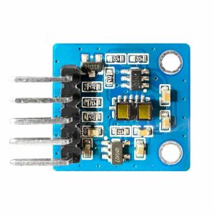
The primary difference between this product and the BML36M001 module is the inclusion of an MCU. Besides incorporating the functionalities of the BML36M001, the product offers configurable alarm thresholds, ranging mode, and a UART interface, providing greater flexibility for users.

Ranging mode

The product provides two ranging modes: long-distance mode and short-distance mode. You can change the modes according to your application.

  1. Long-distance mode allows the longest possible ranging distance of 4 meters to be reached. However, this maximum ranging distance is impacted by ambient light.
  2. Short-distance mode is more immune to ambient light, but its maximum ranging distance is typically limited to 1.3 meters.

If you only need to range distances within 1.3 meters, selecting the short-distance mode will provide more accurate results.

Measurement mode

Users can issue the setMeasureMode() command to enter continuous mode, single mode, or power saving mode.

  1. Continuous mode: retains ranging until users issue a stop command.
  2. Single mode: performs one-time ranging and then automatically stops.
  3. Power-saving mode: ranges every 500ms, each lasting 20ms, until users issue a stop command.

⬥ Refer to 'Arduino Lib Functions' of the Arduino library guide.

Calibration

Referring to the following steps to re-calibrate the product:

  1. Prepare an object with dimensions larger than 10cm x 10cm.
  2. Place the object 140mm away from the product.
  3. Issue the calibration command
    (Refer to the calibrateOffset() and IsCalibration() commands in 'Arduino Lib Functions' chapter of the Arduino library user’s guide).
  4. The calibration process takes approximately 10 seconds. During this time, do not touch the product to avoid affecting the calibration results.
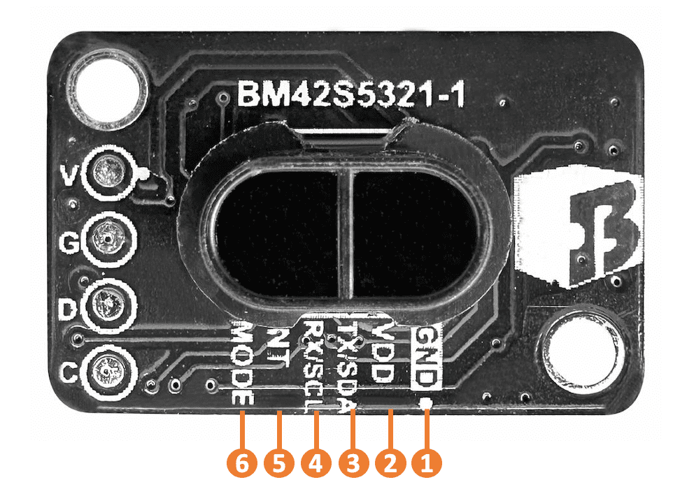
PIN DESCRIPTION

Pin Pin name Function
1 GND Ground
2 VDD Power supply: 3.0V~5.5V
3 TX
SDA
UART: TX
I2C: data line
4 RX
SCL
UART: RX
I2C: clock line
5 INT Triggered: outputs low
Non-triggered: outputs high
6 MODE Interface (UART/I2C) switch pin
RESOURCES
  1. MCU: Holtek HT66F2050, Low Pin Count A/D Flash MCU, including datasheet, package information, etc.
More Information
HS Code (reference) 8517.79.00.00-6
Youtube
Contact Us